PUMPS
Foreword
Pumps are key equipment of most industrial and building systems. Although designed and manufactured to handle the specified conditions for many years, they require careful installation and testing to maximize their performances and longevity.
Disclaimer:
This guide is an overview document aimed at providing the reader with an understanding of the general principles applicable to the subjects listed in the content section below. None of the information provided in this guide is to be seen as a professional advice. Project specific guidelines and specifications must be established by licensed professionals, based on the process and equipment specificities and manufacturers' requirements. The manufacturer's guideline provided in the shop drawings, specifications and manuals always take precedence on the information provided here. SynQ Consulting will not accept any claim of responsibility and will not be held responsible for personal damages and/or material damages and/or liquidated damages and/or any other kind of damage resulting from the use of this guidelines. The reader acknowledges that decisions taken based on the information contained in this guideline remain his/her entire responsibility. The reader recognizes that all specifications, procedures, and activities must meet applicable local laws and codes, the manufacturers' recommendations and be approved by a licensed professional.
Content
The following guide will cover:
- Pump types
- Pumping principle
- Coupling principle
- Pump curve
- Installation and preservation
- Installation on base
- Piping connexion
- Coupling connexion
- API Plan
- Lubrication
- Preservation
- Quality control and Pre-commissioning
- Motor rotation test
- Cold alignment and soft foot
- Cleaning and protection
- Readiness review
- Commissioning
- Start-up
- Performance testing
- Vibration test
Pump types
Pumping principle
The pumping mechanism is of mainly two types: energy is either transferred be mean of added velocity or by direct mechanical work.
Centrifugal pumps are typical of the first type where the energy of the driver is transferred to the fluid by a spinning motion that ultimately accelerates the fluid in a tangential direction.
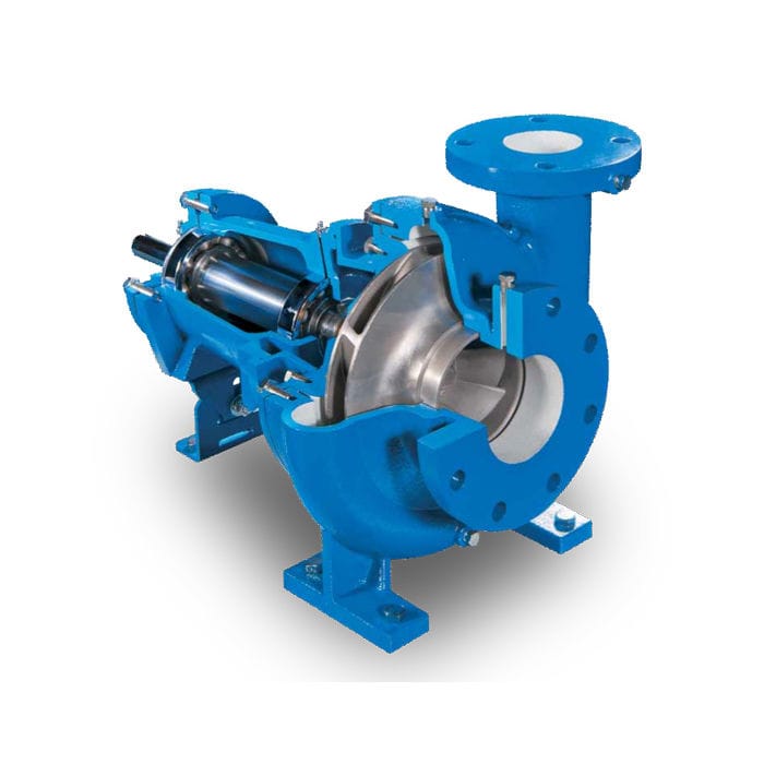
Positive displacement pumps are typical of the second type where a piston, diaphragm, screw, etc. applies a mechanical force and displacement on the fluid.
Coupling principle
Pumps are either of opened (split) or close coupled type. Open coupling means that the pump's shaft is connected to the driver's shaft by mean of a mechanical device, either rigid or flexible, while in close coupled pumps, the pump and the driver share a common shaft.
Closed coupled and rigid (direct) coupled pump and driver share a common enclosure and therefore do not require alignment. However, the motor must fit the enclosure, thus limiting the compatibility and selection range.
Flexible coupled pumps are quieter and can be connected to a wide range of off-the-shelf drivers. However, they do require careful alignment monitoring.
Pump curve
The Pump’s Curve depict the pump's promised performances, as factory tested by the manufacturer.
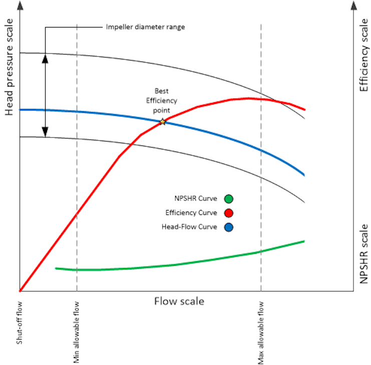
For centrifugal pumps:
One curve shows the pumped volume (flow) in relation to the head pressure. There is three important points on this curve: the shut-off pressure, or the maximum head of the pump at zero flow; the open flow, or the maximum flow at minimum head; the operation point, or the specified efficient head-flow point. Note: pumps shall not be operated at zero-flow. The curve usually indicates the minimum flow requirement to ensure proper heat dissipation.
On many pump curves, several head-flow curves are shown, depicting different impeller size (trim).
Another curve shows the efficiency of the pump, or the relation between the power and the pressure.
The NPSH curve shows the minimum suction pressure required to overcome pump's intake losses and thus, preventing cavitation.
For positive displacement pump, the flow is a function of the pump's speed and the head is fixed, for a given curve. Therefore, the higher the flow, the more power is required. It must be noted that contrary to a centrifugal pump where the pump's speed is the same as the driver's speed, positive displacement pumps are usually connected to the driver be mean of a speed reducer.
Installation and preservation
Installation on base
Manufacturer's manual will provide instruction on how to lift the pump assembly and the number of anchor points required. Assembly must be shimmed to ensure the foot or base plate is leveled and not stressed (see also soft foot in section 3). If not properly leveled, alignment and performances will be impacted. The base must not be grouted until final alignment is completed.
Piping connexion
Suction and discharge piping must be aligned with the pump's nozzles and supported in such a way that no stress (forces) is transferred from the pipe to the body of the pump. Failure to minimize forces on the pump's body will severely impact achieving proper alignment and will significantly increase the requirement for future alignment. Severe stress on the pump nozzles will decrease the lifespan of the pump's bearings and the pump itself by many folds.
Coupling connexion
Coupling must be installed per manufacturer's instructions. Cold alignment verification and soft foot correction is discussed later in section 3.
According to a research project conducted for the Maintenance and Reliability Center at the University of Tennessee, an offset at the far end of the manufacturer's tolerance will lead to a bearing’s life expectancy of 50%. Any greater offset may reduce the life expectancy by a ten-fold factor.
Gland packing and mechanical seal API Plan
Gland packing must not be fully tightened prior to start-up to avoid seizing and ensure proper initial flushing.
Mechanical seal flushing API plan must be installed per manufacturer's instruction, according to the intended process fluid. Improper flushing of the cooling circuit to the mechanical seal may very quickly lead to poor pumping efficiency and/or seal's destruction.
Description and schematic of API plans can be found here: (External link to manufacturer's website)
Lubrication
Lubrication must be performed per manufacturer's instructions. Modern pumps and drivers usually have sealed bearings requiring no initial maintenance. Pump's oil reservoir must be flushed with light oil and then filled to the proper level with approved oil.
If specified, flexible coupling must be greased and protected against the ingression of foreign material.
Since oil shall bever be mixed, to avoid future time-consuming cleaning operations, the responsible contractor shall liaise with the operator to discuss standardizing oil type and brand to facilitate lubricants procurement and management.
Preservation
One critical responsibility of the installer is the maintenance of the equipment from manufacturer's delivery until mechanical completion. All the following applicable activities and those activities mandated by the manufacturer must be performed and recorded:
- When stored in cold or high humidity areas, including when bolted in place, pump and driver must be covered while still ensuring air circulation. Non painted parts must be protected with anti-corrosion oil. When required, heating must be provided;
- At least once a week, shafts must be turn 90 to 120 degrees to avoid bearing spotting;
- Oil must be changed according to time-based maintenance schedule;
- Equipment must be protected from damages and proper house keeping rules must be followed;
- Temporary supports and locks must be kept in place until start-up. It is a good practice to list those elements to be removed on the mechanical completion deficiencies list.
Quality control and Pre-commissioning
By definition, Quality Control activities happen before mechanical completion while pre-commissioning activities happen after. However, this is more a mean of managing responsibilities than it is for timing.
The important element here is that activities happening between the end of the installation and the mechanical completion are to be conducted on non-energized equipment while the pre-commissioning activities may involve energizing the equipment and using safe fluids.
Motor rotation test
Motor rotation test (bump test) objective is to ensure that phases are connected for the motor to turn in the correct direction to drive the connected equipment. The motor rotation test is always conducted with the motor uncoupled.
Safety
This test shall be realized only once all safety electrical tests are fully completed. This includes, but is not limited to: required megger tests, all electrical connexions torquing and all grounding continuity. All power feeding equipment must be fully tested and functional, including, but not limited to: motor drive and/or controller, motor control center, switchgear equipment, local disconnect, all safety protections, all related instruments and indicators. As for any energized equipment, all lock-out and tag-out (LOTO) procedures must be followed and mandatory and/or necessary PPE must be worn.
As the name implies, a bump test involves very short energization phase, most likely a push and immediately release switch type of energization. This will be enough to spin the motor a few turns and visually determine if it rotates clockwise (CW) or counter clockwise (CCW).
Reporting:
In general, the rotation is given as seen from the outboard side, but the manufacturer may have different requirements. Nevertheless, for later reference, it is important to specify if the rotation is reported as seen from the outboard (OB) or inboard (IB) point of view. Therefore, a clockwise rotation, as seen from the outboard point of view shall be reported as: CW-OB. Outboard bearing is the one farthest from the pump, usually on the fan side and the onboard bearing is the one on the pump side, usually the closest to the shaft. Electric motor manufacturers generally use lead end (LE) instead of outboard and shaft end (SE) instead of inboard. When pump rotation is concerned, then the inboard side is the one closest to the driver while the outboard side is the one farthest from the driver. Usually, rotation is expressed from the inlet viewpoint, which is normally located on the outboard side.
Cold alignment and soft foot
Soft foot is a condition where the untightened feet of the equipment are not all fully resting on the base or the shims. When the anchor bolts are tightened, this will lead to stress, deformation or even breakage of the base or equipment's body. Therefore, soft foot must be corrected prior to the torquing of the anchor bolts.
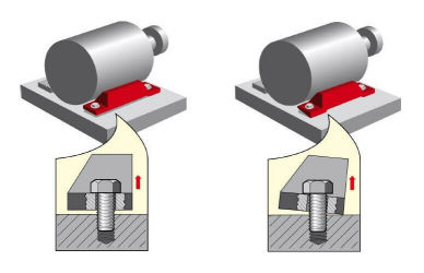
Flexible coupling must be fully aligned prior to start-up. Cold alignment is performed without power to the driver and shafts are turned by hand only. Therefore, the alignment record shall mention any detected issue such as: seized shaft, spotted bearings or hard to turn shaft and necessary corrective actions shall be performed at this time.
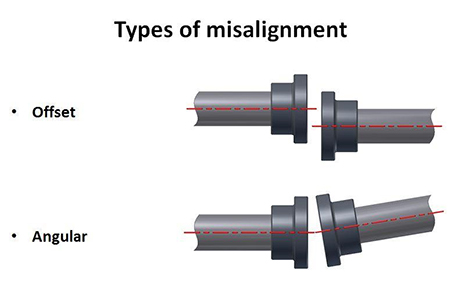
There are several alignment methods now available. Laser alignment with automated instruments is generally preferred for efficiency and precision.
According to a research project conducted for the Maintenance and Reliability Center at the University of Tennessee, an offset at the far end of the manufacturer's tolerance will lead to a bearing’s life expectancy of 50%. Any greater offset may reduce the life expectancy by a ten-fold factor.
Cleaning and protection
While good house keeping and equipment protection shall be enforced all along the project, getting a system ready for start-up mandates a general and careful clean-up of the area to remove all remaining construction material and tools, procure and safely store all required commissioning spares, tools and consumables and install all personal protection equipment.
Safety:
For a system to be deemed ready for start-up, the area must be in operating condition: All personal protection warnings labels, guards and insulation installed, all trips, alarms, interlocks and protections fully functional with, minimally, the local indicators functional. Special care must be given to actively identifying hidden hazards such as forgotten flammable material, unidentified tripping hazards, etc.
Readiness review
Prior to system's acceptance for commissioning, a full inspection and QC records review must be performed per applicable project's procedures. Any missing activity or record shall be listed for correction. In the latter case, system's readiness is at the commissioning manager's discretion.
Commissioning
Start-up
Safety:
In addition to the above readiness preparation, all necessary training of attending personnel must be completed and a comprehensive job safety analysis must be completed by all attending personnel, every day for each applicable system.
Starting-up a pumping system implies that a safe power supply, a system to pump from and an equipment to pump to are available. Other dependencies may be required depending on the complete system's process. For example, if the pumped fluid is passing through an exchanger, it may be required for the service side to be functional too. Once the readiness review of the system is completed and all dependencies are confirmed, the start-up phase can begin.
Performance testing
Initial pump start-up should be done in manual mode and each pump should be ran for only a short duration to ensure there is no excessive vibrations and unusual noises present; the packing or seal are not leaking (a minimal leakage is normal, but is should not puddle on the floor) or heat too much (see manufacturer's specifications for applicable threshold).
Then, pump's performances can be checked against the pump curve by running at 5 flow points: minimum flow; between minimum flow and operation point; operation point; between operation and full flow; full flow. When plotting the measured head for each point, it should fall very close to the curve. At each point, a voltage and current take-off must be done to assess the real power consumption and correlate it to the power curve.
If results are off curve, the manufacturer's troubleshooting guide must be initiated.
As a kick-starter only:
Vibration is likely caused by bad alignment, spotted, or damaged bearings. Low head alone is likely caused by an incorrect impeller size, reversed rotation, or cavitation (low NPSH). High power consumption is likely cause by flow restriction, seized packing, seal or bearing or bad motor. Causal part will most likely overheat or make noise.
Vibration test
The easiest way to ensure pump's reliability after start-up and avoid performing several unnecessary hot alignments is to setup vibration monitoring for several running hours. Any slight misalignment will result in a characteristic vibration spectrum as well as failing bearings. Vibration testing is also an efficient preventive maintenance tool.